Here is the link to his site. http://www.prismnet.com/~nielw/tnt/tnt.htm
The "TPTG", or "Tuned-Plate-Tuned-Grid" transmitter is a self-controlled type oscillator in which the interelectrode capacitances of the tube or tubes provide the necessary feed-back paths to sustain oscillations. One problem with the basic TPTG configuration is that the frequency one is transmitting on is determined by the tuned circuit with the higher "Q", and this can often result in difficulty getting the transmitter on a particular frequency and keeping it there. One way to eliminate this problem is to build it so that the grid-side tuned circuit is low "Q", fairly broad-band, using fixed components, and to build the plate-side tuned circuit with as high "Q" as reasonable. This is then called the "TNT" or "Tuned-Not-Tuned" circuit.
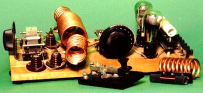
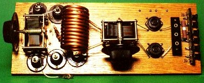
Shown below are photos of the very nicely built TNT rig which is described by the builder, Niel Wiegand, W0VLZ, at the link below the photos.
Here is the link to his site. http://www.prismnet.com/~nielw/tnt/tnt.htm
The photo below shows Jack Meadows, W7QQQ's, Push-Pull pair of 809s in the TPTG configuration.
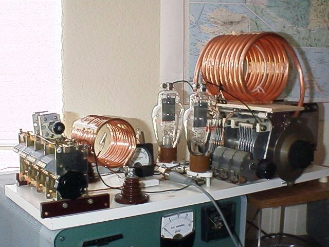
I have worked this rig on 80 meters, and is usual with Jack's other rigs, it sounds really beautiful. No chirp, nor clicks, nor drift. It has a beautiful bell-like sound when keyed.
I will post schematics and photos of my Push-Pull pair of 211s in the TPTG configuration as soon as I get it finished.
One thing that should be kept in mind concerning TPTG rigs: as mentioned above, the frequency that the transmitter operates on is determined by that tuned circuit with the higher "Q". Therefore, it is best to build either the grid circuit or the plate circuit with much lower "Q" than the other. Otherwise they "fight" and it becomes difficult to tune to a particular frequency. Since the "Q" of the plate circuit ultimately determines the harmonic output, the plate circuit, therefore should have the higher "Q". In my rendition of this classic rig, I have built the grid circuit to have much lower "Q" than the plate circuit. Thus the much smaller diameter coil made of higher resistance (smaller) wire, and a lower C to L ratio. Using a TPTG configuration instead of the TNT configuration allows some adjustment in operating frequency.
Here is a photo of my partially finished TPTG rig:
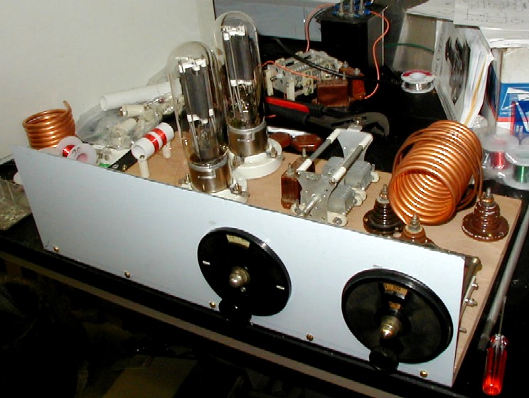
I have yet to mount the grid-tuning capacitor, its vernier, and the surface-mounted meter to the left of the plate-tuning capacitor. I also plan to stain and finish the nice piece of Phillipine Mahogany on which I have mounted the various bits.
And here is the schematic of the transmitter:
