The classic Hartley single-tube transmitter. This particular circuit is one taken nearly verbatim from an article in March 1932 issue of QST, written by George Grammer. There are some slight modifications to the circuit by Bob Keys, NA4G, of Glowbugs fame. He has tamed the circuit, and suggested to the members of the GLOWBUGS list that any triode could be used in this circuit, PROVIDED it was VERY lightly loaded, the biasing resistor, grid tap on the coil, and plate voltage are adjusted so that the tube provides about 10% of its usual ICAS ratings, and that the coil was appropriately sized to the tube. The power supply must be very "stiff", i.e. well regulated to minimize chirp from that source. With the tube here shown, the transmitter puts out about 5 watts. The circuit constants for L1, L2, C1 and C2 are correct for 160 meters. For 80 meters, divide all values (coil turns and capacitance) by 2. If you would rather leave the capacitor values unchanged, divide the coil turns by 4, but this would make for very fast tuning.
This circuit would work fine for the Antique Wireless Association's "1929 QSO Party".
If this transmitter is properly built, following the above suggestions about keeping the power-output low, and using a properly regulated power supply, the signal output should sound quite good. Dynamotors or MG-sets would be perfect. If the builder/user does not follow the recommendations, the signal will be extremely chirpy and hard to copy.
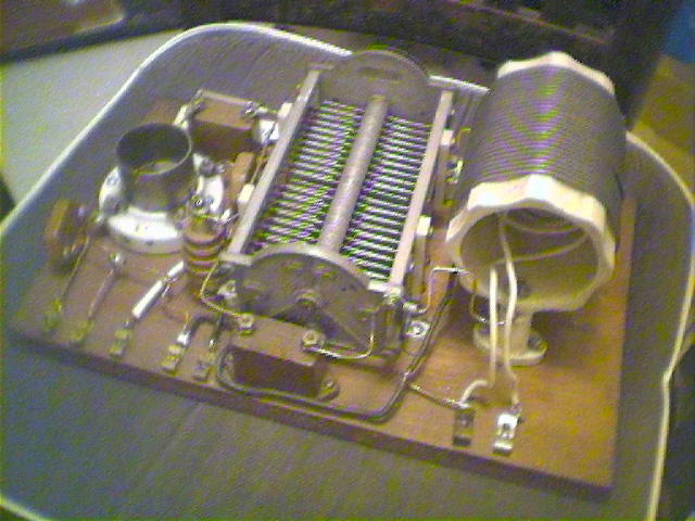
Roy Morgan's, K1LKY, ancient Hartley. This rig was built back in the 1930s and uses a type 203A tube. Roy has gotten a 203A since this photo was taken. Note the very large components.
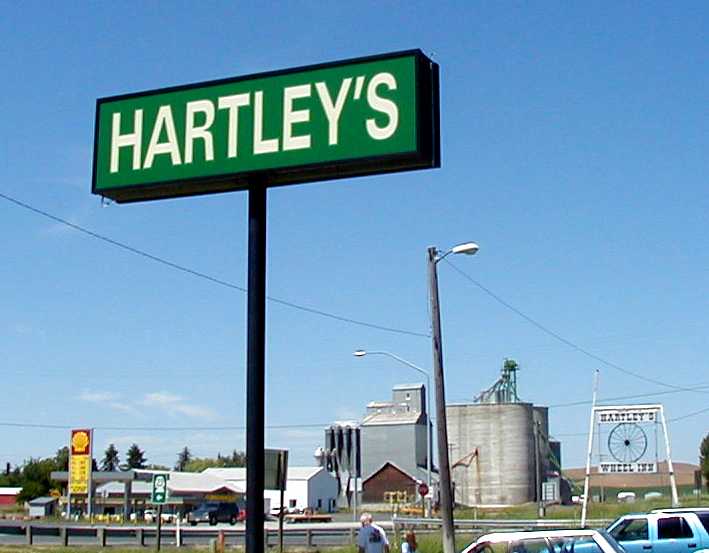
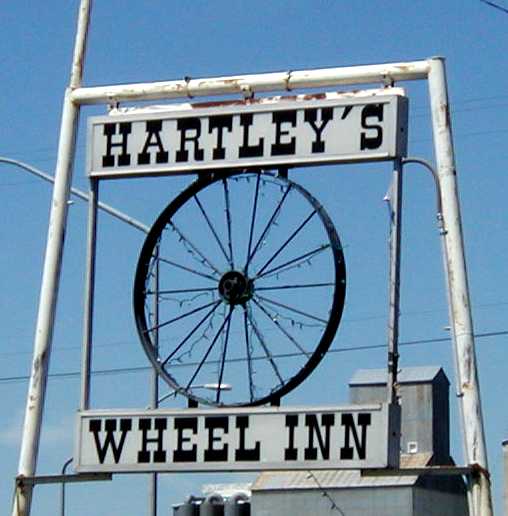
This was a restaurant near Colfax, Washington on Highway 195, south of Spokane, Washington, now torn down.