|
The Selectoject is a receiver adjunct that can be used as a sharp amplifier or as a single-frequency rejection filter. The frequency of operation may be set to any point in the audio range by turning a single knob. The degree of selectivity (or depth of the null) is continuously adjustable and is independent of tuning. In phone work, the rejection notch can be used to reduce or eliminate a heterodyne. In C.W. reception, interfering signals may be rejected or, alternatively, the desired signal may be picked out and amplified. The Selectoject may also be operated as a low-distortion variable-frequency audio oscillator suitable for amplifier frequency-response measurements, modulation tests, and the like, by advancing the "selectivity" control far enough in the selective-amplifier condition. The Selectoject is connected in a receiver between the detector and the first audio stage. Its power requirements are 4 ma. at 150 volts and 6.3 volts at 0.6 ampere. For proper operation, the 150 volts should be obtained from across a VR-150 or from a supply with an output capacity of at least 20 mf. The wiring diagram of the Selectoject is shown in Fig. 5-45.Resistors R2 and R3, and R4 and R5, can be within 10 percent of the nominal value but they should be as close to each other as possible. An ohmmeter is quite satisfactory for |
doing the matching. One-watt resistors are used because the larger ratings are usually more stable over a long period of time. If the station receiver has an "accessory socket" on it, the cable of the Selectoject can be made up to match the connections to the socket, and the numbers will not necessarily match those shown in Fig. 5-45. The lead between the second detector and the receiver gain control should be broken and run in shielded leads to the two pins of the socket corresponding to those on the plug marked "A.F. Input" and "A.F. Output." If the receiver has a VR-150 included in it for voltage stabilization there will be no problem in getting the plate voltage - otherwise a suitable voltage divider should be incorporated in the receiver, with a 20- to 40-mfd. electrolytic capacitor connected from the + 150-volt tap to ground. In operation, overload of the receiver or the Selectoject should be avoided, or all of the possible selectivity may not be realized. The Selectoject is useful as a means for obtaining much of the performance of a "Q Mulitplier" for a receiver lacking one. |
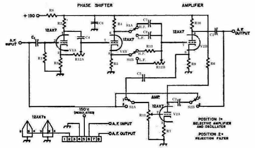
Fig. 5-45 -- Complete schematic of Selectoject using 12AX7 tubes.
|
C1 -- 0.01-µf. mica, 400
volts. |
R6 -- 20,000 ohms. ½ watt. |
![]() Back to Receivers:
Back to Receivers: