| The Vackar variable-frequency oscillator
appears to have some advantages over the usual Clapp (1) circuit. In the
latter, the output amplitude varies greatly with frequency. In the Vackar
circuit, the output varies only a little with frequency. The useful frequency
range of the Clapp circuit is about 1.2 to 1; in the Vackar it is about
2.5 to 1. The first of these advantages should be of interest to amateurs.
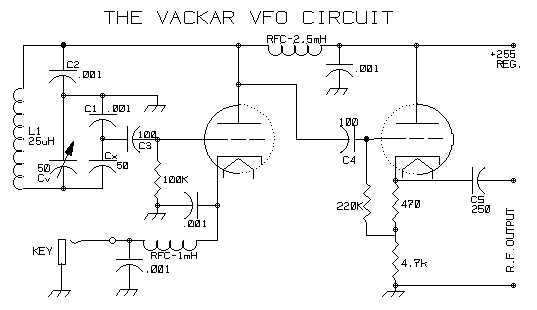
My friend and colleague, Mr. James B. Ricks, W9TO, has pointed out that the 6AG7 is not the best tube to use for a series-tuned v.f.o.; indeed the several papers originally describing these circuits invariably show triodes. The best tube is that one which has the lowest ratio of change of input capacitance to its mutual conductance. The operating mutual conductance for the cathode, control grid, and screen grid of a 6AG7 (as typically used as an oscillator) is low, despite its high value for the normal grid-to-plate circuitry. Also, it has a high input capacitance and high heater and plate power inputs. In consequence, this tube is not ideal for the purpose. A small dual triode, the 12AT7, offers higher oscillator gm in one triode section, lower input capacitance, and about one third the heater and plate power inputs required by the 6AG7. In consequence, it is a superior tube for series-tuned oscillators. The output voltage will be lower for the 12AT7, naturally, but a tube should not be evaluated for v.f.o. use on the basis of power output. W9TO has adapted the Vackar circuit to an amateur v.f.o. with output on 80 meters using the 12AT7 in the circuit of figure below. The first triode unit and its associated components form the oscillator proper; the other triode unit is a cathode follower which reduces loading effects on the oscillator frequency Two of these v.f.o. units have been made and tested; their frequency stability is excellent, and they key well. The output r.f. was measured as 1.2 volts r.m.s. using a General Radio v.t.v.m. The total current from the 255-volt regulated B supply was 16 ma., key down. |
In series-tuned oscillators of the Clapp or
Vackar type the characteristics of the series capacitor Cx are critical
if the oscillator is to be keyed. An annoying chirp, slight but detectable,
was finally traced to imperfection of this capacitor, even though it was
a low temperature coefficient silvered mica one. Several silvered micas
of good make were tried; they all produced slight chirp, some less than
others. A so-called zero temperature coefficient (NPO) ceramic capacitor
gave less chirp (very little, in fact), but the chirp was eliminated by
using an APC air trimmer for Cx. Apparently, there is enough r.f.
current through Cx to cause dielectric heating and a small resulting
change in capacity even in these high-grade capacitors. This, was confirmed
indirectly by using for C1 a negative temperature coefficient (N750) ceramic
capacitor. The chirp was tremendous!
Of course, the series capacitor is not the only possible cause of chirp; poor plate voltage regulation or a long time constant in the keying circuit might also contribute. To avoid this, the plate supply should be regulated, and series resistances and shunt capacitances in the keying circuit should be kept to a minimum.(2) The circuit shown will key cleanly without chirp; with the constants shown it will be somewhat clicky, due to turning on and off rapidly; this makes it very desirable for use in a differential keying system in which the oscillator is turned on before the amplifier, and the amplifier is turned off before the oscillator. W9JK ___________________________________ (1) Clapp, J. K., "Frequency. Stable LC Oscillators," Proc. of the LR.E., Aug., 1954, Vol. 42, No. 8, page 1295. (2) The chirp discussed in the preceding paragraph evidently is a slow one attributable to temperature effects. A chirp of the "dynamic" type often manifests itself as a click when the time constant of the keying circuit is very short, becoming observable as a chirp when key-thump elimination methods are used. Ed. This material originally appeared in QST for November, 1955. Ed |
The Vackar series-tuned v.f.o. circuit at W9TO. The tube is a 12AT7 dual triode. R.f. output from the cathode-follower second section is 1 .2 volts r.m.s.C2 Silver mica.
C4, C5 Mica.
Cx APC air variable.
Other capacitors are ceramic.