14 - 600 Khz.
14 - 600 Khz.
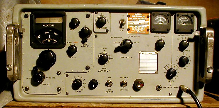
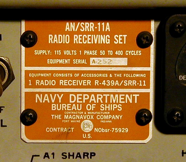
Here is a 1960s era U.S. Navy shipboard VLF receiver, the RCA designed and built AN/SRR-11A. This fairly small receiver none-the-less weighs 69 lbs, and is about 3/5 as high as an R-390. It contains a 28 tube dual-conversion (60 Khz, and 200 Khz IFs), superheterodyne receiver of unique construction. It is very highly modularized, making service much easier than for most other receivers, and uses sub-miniature tubes throughout, which were designed for extreme reliability. The tubes are soldered into miniature modules which are then plugged into modular sections, i.e. ANT, RF, MIXER, OSC, 1st IF, IF, AUDIO, CALIBRATOR, POWER SUPPLY, etc.
The receiver covers the range 14 - 600 Khz, in five bands, 14 - 30 Khz, 30 - 63 Khz, 63 - 133 Khz, 133 - 283 Khz, and 283 - 600 Khz. There are 3 modes of operation, A-1 (CW or SSB) Broad, and Sharp, A-2 (AM), and F-1 (RTTY). There is a diode detector for the A-2 mode, and an automatically switched-to "BFO-Mixer" for the A-1 and F-1 modes. The BFO-Mixer is actually a product detector, making CW and SSB operation a snap. There is an automatic noise limiter for the modes which use the BFO-mixer, and an adjustable peak-limiter in the audio stage.
Selectivity of these receivers is excellent, the -A models being the best. They have a really good band-pass filter in the 1st IF stage, 2.6 Khz at -6 db and 3.7 Khz at -60 db. There are two other filters in the following 2nd IF stage, "sharp", with 2.4 Khz BW, and "medium" with 8 Khz BW. Lastly, there is a 350 Hz audio filter in the audio stage between the 1st and 2nd audio amps.
Antenna input impedance is easily changed from High Impedance (approximately 300 ohms) to Low Impedance (approximately 70 ohms) by means of an internal jumper.
There are outputs on the rear panel for an IF connected RTTY converter such as the CV-57/URR, AC power, RF input (an "N" connector), and two audio outputs for connection to an external audio amp/speaker or to an audio-type RTTY converter such as the CV-60/URR. These audio outputs have their own front panel Output control.
Connectors for the rear-panel connections are standard Amphenol Mil 97-3106A type connectors available from Newark and other parts suppliers. I bought mine from Newark.

All inputs and outputs are very effectively filtered by integral robust band-pass filters so that the receiver is isolated from nearby transmitters or other spurious signals.
Audio output is by either two front-panel mounted 1/4" phone jacks with their own separate Level Control, or as mentioned above, via rear panel mounted connectors to an external speaker or audio amplifier, or RTTY converter.
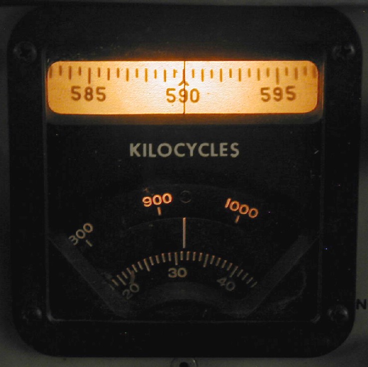
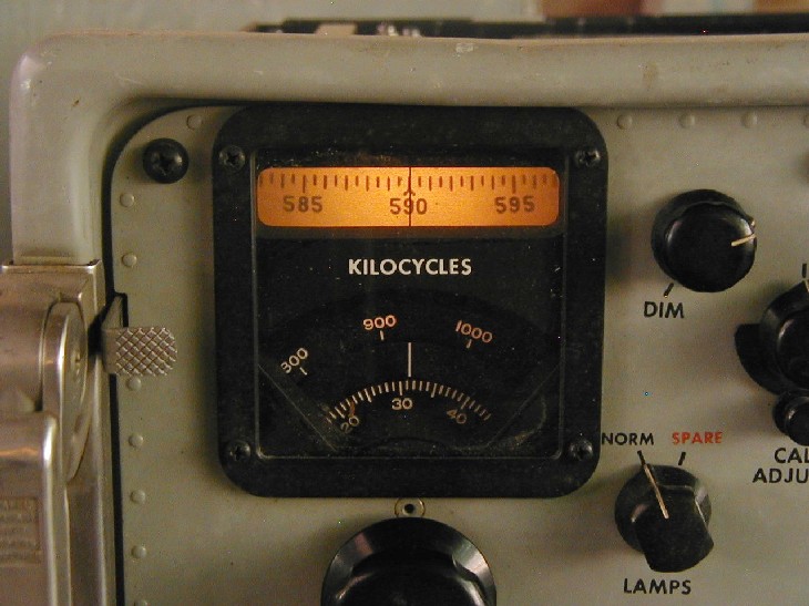
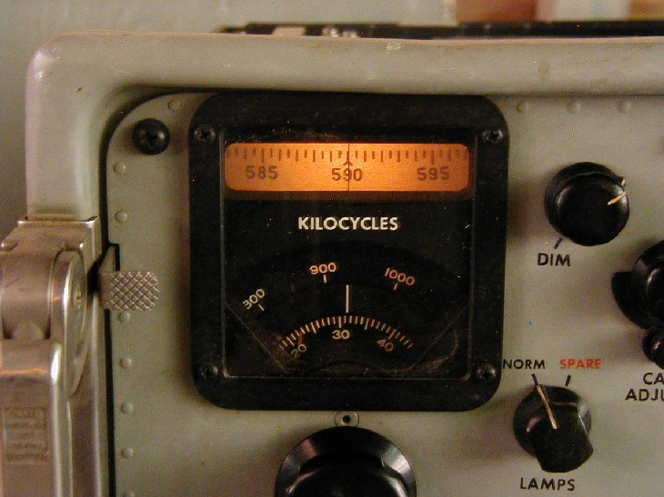
The very accurate dial readout mechanism is quite unique in that it is uses a projection system and an etched glass disk giving an effective linear analog readout of approximately 12' (feet) in length, combined with an extremely accurate and easily resettable logging scale. The direct-frequency dial readout is actually much darker and clearer than my photo indicates, but it was the best I could do.
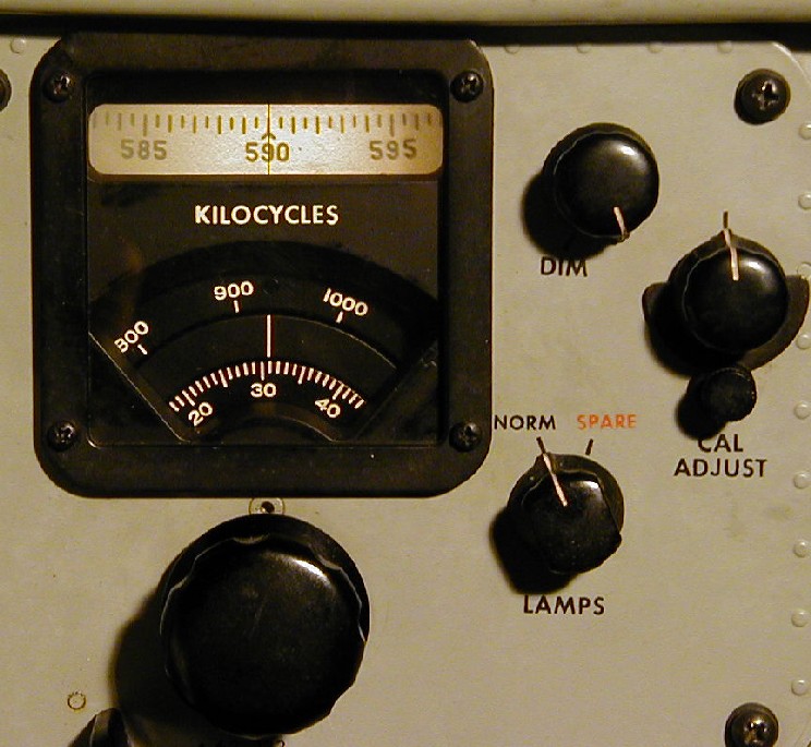
Here are some other photos of the dial, taken with the dimmer control adjusted for less and less light output. I really like the nice golden color as it gets darker.
There is a built-in accurate 10 Khz., crystal calibrator of unique design which switches all outside signals away when it is switched on.
The built-in power supply accepts 105, 115, and 125 VAC at 50 to 400 Hz, and provides regulated and unregulated voltages for the receiver.
This particular receiver is in pretty decent cosmetic condition, although the case is pretty scratched up and dirty. Electrical/electronic condition is quite good, although as with any other receiver of this age, its alignment should be checked and tweaked. Interior is clean and it works properly on all bands and modes. The previous owner added a front-panel mounted RF gain control, which can be easily removed if one wishes to restore the receiver. This receiver has had all the factory modifications done to it, i.e., the power supply has solid-state diodes in place of the original two 6X4 rectifier tubes, and 5 of the 6 5647 diode tubes have been replaced with 1N458 diodes. Also, the Antenna (1st RF amp) and RF amp (2nd RF amp) stages have been modified to give increased gain and stability.